The Niagara range of Wet Surface Air Coolers are efficient and durable closed-loop, evaporative coolers and condensers, used in liquid cooling, single phase gas cooling and turbine exhaust vacuum steam condensing applications. Each WSAC cooler or condenser is custom-designed to fit the specific application, and are tailored to meet the unique needs of the most demanding applications.
Proven philosophy for lower temperatures
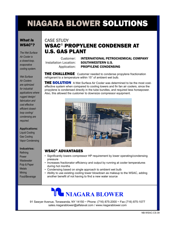
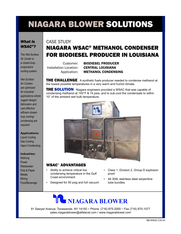
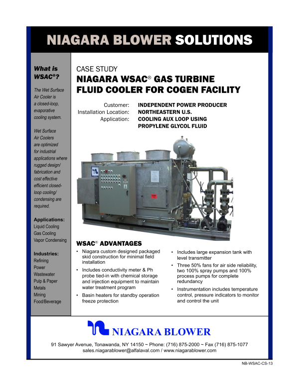
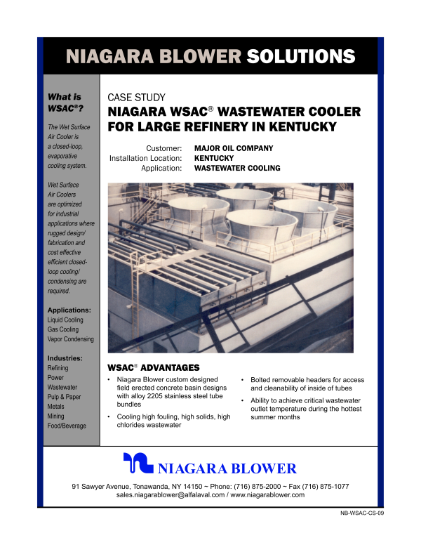
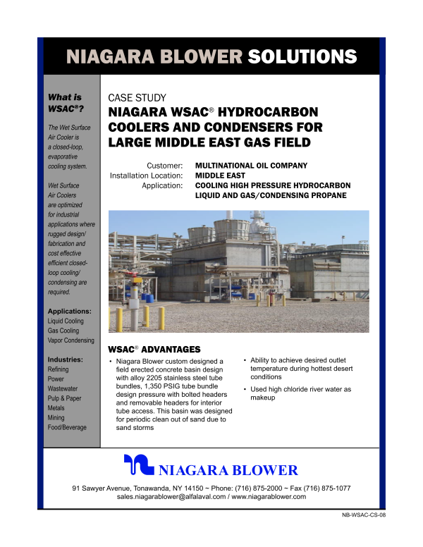
Alfa Laval Niagara Wet Surface Air Coolers (WSAC®) are efficient closed-loop, evaporative cooling systems designed for the power, process, wastewater, natural gas and petrochemical industries. These fluid cooling and vapor condensing systems are optimized for industrial applications where rugged designs, and cost-effective, efficient closed-loop cooling and condensing duties are required.
The Alfa Laval Niagara WSAC system is one of the most efficient and durable evaporative coolers available – capable of cooling process fluid to within 5°F of the surrounding wet bulb temperature. Our wet surface air coolers are constructed with heavy gauge steel double brake flanged on all four sides, and welded in all corners – providing extreme rigidity, extending service life and increasing overall durability to customers worldwide. Our WSAC system offers improved efficiencies over traditional heat exchangers used throughout the industries.
How it works
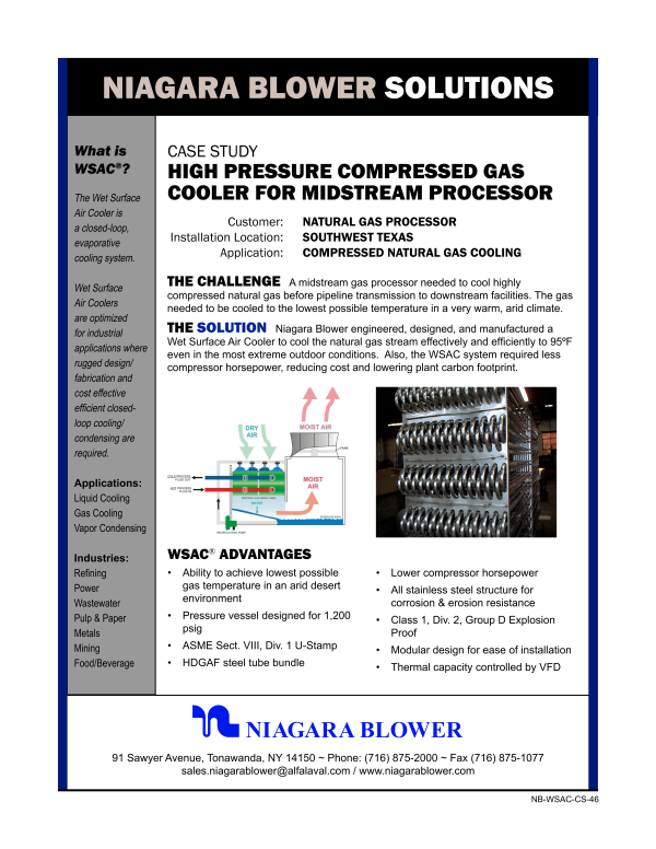
In a WSAC® system, warm process fluids or vapors are cooled in a closed-loop tube bundle (the process fluid being cooled never comes in contact with the outside air). Open loop water is sprayed and air is induced over the tube bundle resulting in the cooling effect.
Air is induced downward over the tube bundles.
Water is sprayed over the bundles, and travels downward along with the air.
A warm process stream (liquids, vapors, or hydrocarbons) flows through tube bundle. Heat from the process stream is released to the cascading water, and a cooled process stream exits.
Vaporization transfers heat from cascading water to the air stream.
The air stream is forced to turn 180° providing maximum free water removal
Fans discharge air vertically at a high velocity to minimize recirculation
WSAC systems to suit the most demanding applications
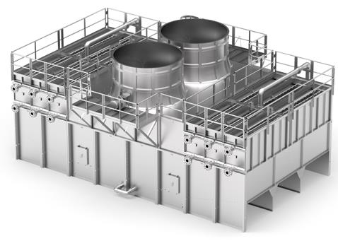
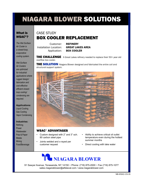
The Niagara Wet Surface Air Cooling systems (WSAC®) are designed and built for rugged and long lasting industrial applications. Niagara uses heavy gauge steel construction which is double brake flanged on all four sides and welded in all corners providing extreme rigidity, extended service life and durability. All metal fabrication is completed and tested in Buffalo New York before shipment to the job site.
Two variations
Prepackaged Niagara units are designed as a single skid with no field assembly required. These units can be shipped directly to the job site for easy and immediate installation.
Field erected units are the largest design type Niagara offers. Constructed using either concrete or FRP (Fiberglass Reinforced Plastic), field erected Niagara units offer the ability to cool high volumes of process fluid in a smaller plot area (footprint) than a traditional cooling tower. Observation and maintenance of the spray water distribution system can be accomplished without structure entry, fan shut down, or pump shutdown, providing 24 hour operation. Access doors and hatches also allow for cleaning and inspection of the lower water basin.
Material construction
Standard Niagara units are Hot Dipped Galvanized After Fabrication (H.D.G.A.F) according to ASTM A123. Zinc provides 42% more fighting resistance to rust and corrosion versus raw exposed steel. Dipping insures that all surfaces and machined edges are well coated. Niagara's competitors use mill galvanized material which results in a significantly thinner layer of zinc and less protection against material degradation.
Since Niagara engineers every job from scratch, almost any material can be specified. Niagara offers optional 100% stainless steel construction and thick walled tubes for maximum protection and service life. Other materials include titanium, brass, copper, and more.
Custom tube bundles
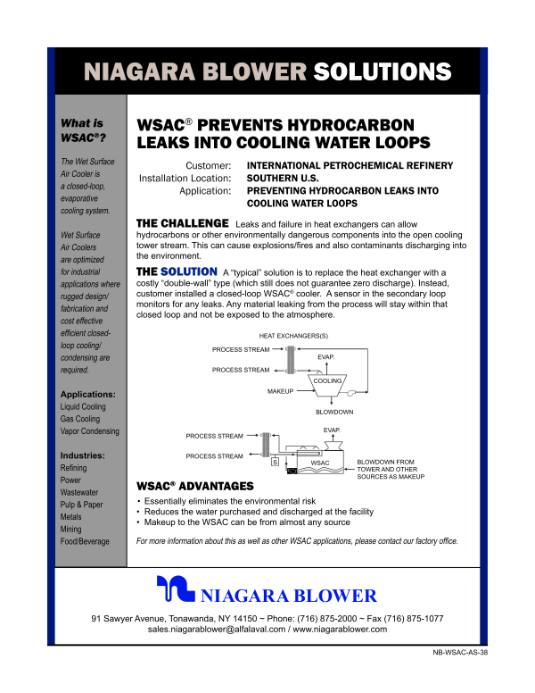
Niagara WSAC® systems are “closed-loop” which means that the process stream being cooled or condensed is never exposed to ambient air where airborne matter can contaminate it. Cooling tubes can be designed either in a serpentine or straight through and cleanable bundle depending on service requirements.
Tube bundles can sustain an operating pressure of 2500psi and can be designed in accordance with ASME code standards with all materials in contact with the process stream having full ASME material certification. Existing piping can be arranged and valved so that any tube bundle can be taken out of service for maintenance while the unit is operating.
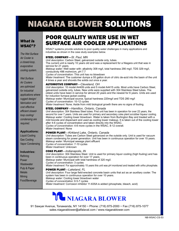
Poor quality makeup water
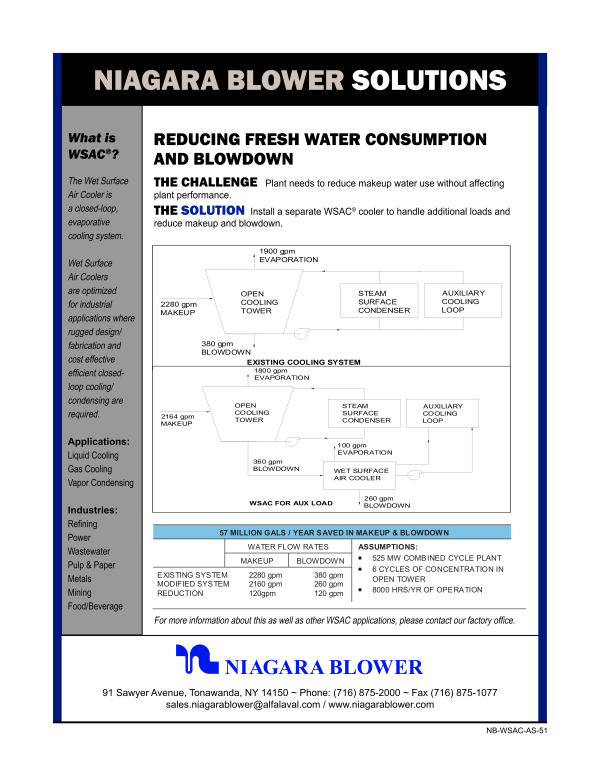
With the growing concern of water usage, Niagara WSAC® systems can use poor quality water as spray to reduce fresh water consumption. Typical examples of water sources include blowdown from existing cooling towers, wastewater, river water, pond water, etc. Wide tube spacing in conjunction with low pressure/high volume nozzles allows spray water to be run at high cycles of concentration, up to 50 cycles in some cases, thereby reducing water consumption up to 70% annually.
High efficiency fans
All fan assemblies are designed to give maximum fan efficiency and long life when handling saturated air at high velocities. A WSAC® unit is sized to reject heat at the most difficult condition: full heat load at the highest expected wet bulb air temperature. Most WSAC® fans operate in on or off modes with the fans automatically switching Off when the process outlet temperature begins to drop. Individual blades are adjustable pitch and can be either cast aluminum or FRP. Fans smaller than 5 foot diameter are directly connected to marine duty, Totally Enclosed Air Over (TEAO) motors. Fan greater than 5 foot diameter fan utilize TEFC, NEMA approved motors with fiberglass reinforced epoxy fin blades. Fan stacks are installed with access doors for system maintenance and inspection.
Accurate temperature control
Changing the air flow rate over the tube bundles very effectively controls the fluid outlet temperature. Multiple fans operating in parallel are used to induce the required air volume needed to evaporate the application’s heat load (as opposed to a single large diameter fan). This allows utilization of a number of different process temperature control schemes.
Variable Frequency Drive (VFD) fans can be used to increase or decrease the air flow rate depending on the process outlet temperature. The precision of a VFD is greater than the on/off scheme and can maintain outlet temperatures at +0 / -2.5 degrees F relative to the set point. VFDs can reduce the air rate automatically when the process outlet temperature begins to drop due to lower heat loads or reduced wet bulb temperatures.
Simple RTD monitoring of outlet fluid temperature can be combined with logic control so to effectively modulate heat rejection capacity of the WSAC®. Inlet vs. outlet temperature monitoring (delta T – cooling range) can permit capacity control functions to further improve response times relative to the set point.
Induced draft
The Niagara units are induced draft co-current flow. Because of this arrangement, the pressure inside the casing and coil section is negative. Negative pressure is the best way to uniformly distributing of air over the tube bundles. The co-current flow (air and spray water traveling in the same direction) also insures proper distribution of the spray water over each tube. In counter-current flow, turbulent spots on the tubes prevent water from covering the entire tube surface. This causes hot spots that lead to deposits and scaling, thus affecting performance over time. Niagara’s high velocity discharge prevents recirculation of moist air back into the inlet of the unit. Additionally the Niagara arrangement does not require drift eliminators. Since there is no pressure drop across the drift eliminator section, as much as 15% less fan energy is required.
High velocity discharge
Niagara discharges the saturated air at high velocity to prevent recirculation back to the inlet of the unit. Even with a high discharge rate, Niagara’s tube bundle and fan arrangement does not require drift eliminators. This is due to the two 90 degree turns the air is forced to make before being exhausted. Most of the water drops out of the air-stream before it reaches the fans. Since there is no pressure drop across the drift eliminator section, as much as 15% less fan energy is required.
Drenching spray system
Spray water distribution employs a low pressure high flow design with full flood spray pattern to provide optimum tube bundle drenching. Inspection and service of the spray nozzles can be accomplished without removing any appurtenances while the equipment is in operation. Access packages and walkways are available from Niagara to further assist maintenance personnel with nozzle and bundle inspection. The spray system will also be arranged so that an individual tube bundles may be hydraulically isolated for service or control.
Hardware
Niagara construction employs drill through holes with nut and bolt fasteners. Drill through hardware sustains a much longer service life versus self tapping metal screws.
Low energy usage
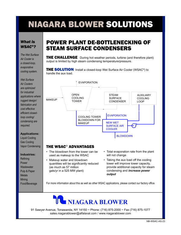
The co-current design of the Niagara WSAC® system does not require mist eliminators to remove the water droplets from the discharge air stream. Mist eliminators increase the static pressure load by approximately 15%. This increased pressure drop requirement directly equates to higher power consumption. The Niagara WSAC® cooler or condenser also has a lower unit profile which reduces the spray water pumping head requirement by approximately 20%.
Niagara engineers have been providing cooling solutions for over 100 years for a wide variety of clientele. Each WSAC® cooler or condenser is custom designed to fit a particular application. Design parameters are based on customer specifications for input and output temperatures as well as average weather conditions. All WSAC® units are tailored to meet the unique needs of the most demanding applications in the world.
-
nb-wsac-cs-39-propylene-condenser.pdf
459 KB
瑞典
-
nb-wsac-cs-50a-improved-efficiency-gas-processing_benefits.pdf
526 KB
瑞典
-
nb-wsac-cs-45-hybrid-cooler.pdf
540 KB
瑞典
-
nb-wsac-cs-53-poor-quality-water-use.pdf
162 KB
瑞典
-
nb-wsac-cs-42-steam-condenser.pdf
1310 KB
瑞典
-
nb-wsac-cs-48-well-injection-co2-coolers.pdf
224 KB
瑞典
-
nb-wsac-cs-37-wastewater-cooler.pdf
267 KB
瑞典
-
nb-wsac-cs-14-vapor-condenser.pdf
252 KB
瑞典
-
nb-wsac-cs-12a-wastewater-cooler_additional-information.pdf
117 KB
瑞典
-
nb-wsac-as-40-wastewater-evaporation.pdf
227 KB
瑞典
-
nb-wsac-as-56-mud-cooler.pdf
529 KB
瑞典
-
nb-wsac-cs-50b-improved-efficiency-gas-processing_benefits.pdf
521 KB
瑞典
-
nb-wsac-as-32-wsac-vs-air-cooled-hx.pdf
133 KB
瑞典
-
nb-wsac-as-41-water-saving.pdf
140 KB
瑞典
-
niagara-service-and-parts.pdf
169 KB
瑞典
-
nb-wsac-as-21-reduce-h20-consumption-power-plant.pdf
155 KB
瑞典
-
nb-wsac-cs-16-gasoline-cooler.pdf
631 KB
瑞典
-
nb-wsac-cs-43-methanol-condenser.pdf
336 KB
瑞典
-
nb-wsac-cs-54-glycol-cooler-mining.pdf
497 KB
瑞典
-
nb-wsac-cs-15-aux-loop-cooler.pdf
680 KB
瑞典
-
nb-wsac-as-39-flow-diagram-ngl-fractionation.pdf
144 KB
瑞典
-
nb-wsac-cs-47-green-wastewater-cooler.pdf
239 KB
瑞典
-
nb-wsac-as-25-efficiently-cool-or-condense.pdf
384 KB
瑞典
-
nb-wsac-cs-50-improved-efficiency-gas-processing.pdf
430 KB
瑞典
-
nb-wsac-cs-49-gas-compressor-station.pdf
1543 KB
瑞典
-
niagara-wsac-faqs.pdf
182 KB
瑞典
-
nb-wsac-as-38-prevent-hydrocarbon-leaks.pdf
199 KB
瑞典
-
nb-wsac-cs-13-turbine-fluid-cooler.pdf
308 KB
瑞典
-
nb-wsac-cs-09-wastewater-cooler.pdf
1172 KB
瑞典
-
nb-wsac-cs-52-propane-condenser.pdf
595 KB
瑞典
-
nb-wsac-cs-08-hydrocarbon-cooler.pdf
1228 KB
瑞典
-
nb-wsac-cs-24-vapor-recovery.pdf
521 KB
瑞典
-
nb-wsac-cs-09a-wastewater-cooler_additional-information.pdf
1229 KB
瑞典
-
nb-wsac-cs-46-compressed-gas-cooler.pdf
335 KB
瑞典
-
nb-wsac-cs-09a-wastewater-cooler_additional-information (1).pdf
1229 KB
瑞典
-
nb-wsac-as-55-frp-modular.pdf
390 KB
瑞典
-
nb-wsac-as-51-reduce-h20-consumption.pdf
163 KB
瑞典
-
nb-wsac-cs-35-box-cooler.pdf
631 KB
瑞典
-
nb-wsac-cs-16-gasoline-cooler.pdf
631 KB
瑞典
-
nb-wsac-as-31a-aux-loop-cooler.pdf
314 KB
瑞典
-
nb-wsac-as-23-power-plant-de-bottlenecking.pdf
189 KB
瑞典


 简体中文
简体中文
 English